By Paul O’Hearn, engineering manager, Profile Plastics
Adding decoration to injection-molded parts not only increases the attractiveness of plastic products, but also functionality and value. The inherent durable nature of appliques or ink transfer process, coupled with the ever-expanding decorative options and addition of functional electrical circuits, provides original equipment manufacturers with a multitude of product options with a long service life.
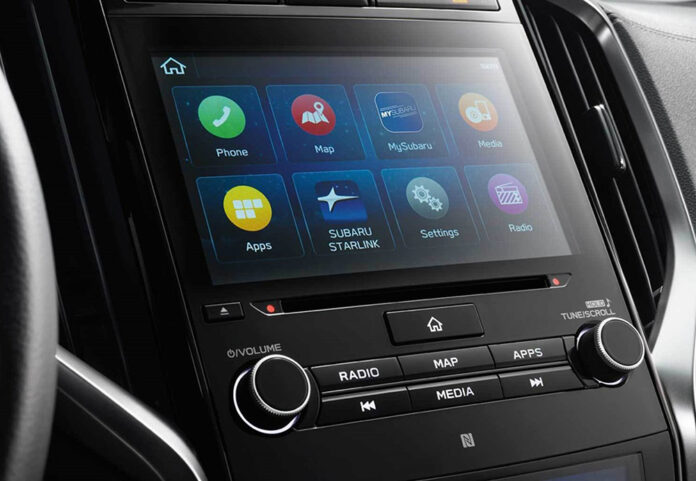
Automotive interiors, large appliances, medical devices and consumer products are just some of the potential markets for durable in-mold decorated components (see Figure 1). But properly designing an injection-molded part and the resulting tooling can be complex, as modifications to traditional molded part design and additional in-mold specific considerations are required for the project to be successful.
Before this article gets into the details of how to design a durable part for in-mold decoration, let’s talk first about some definitions used to describe the various decoration processes.
In the durable goods arena, the term in-mold labeling (IML) often is used interchangeably with film insert molding (FIM). This process consists of a screen or digitally printed film that is thermoformed, diecut and placed into a cavity to be molded. The decorated film stays with the molded part when delivered to the customer.

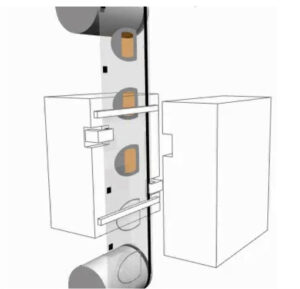
In-mold decorated (IMD) parts use a roll-to-roll heat transfer process like Kurz or Nissha. A gravure printed roll of film passes through the parting line of a specially designed mold, is indexed and located using a specialized film feeder mounted to the platen of the molding machine (see Figure 2). The carrier film with decoration is formed to the cavity geometry using vacuum. Only the decoration ink layers are transferred from the carrier film to the resin during the molding process, and the carrier film is no longer present on the part after molding.
In-mold electronics (IME) refers to the addition of electrical components such as LEDs and conductive traces to the appliques that add functionality, including capacitive touch or indicator lighting. Typically, IME is executed using the IML process.
General Part Design and Specification Considerations
For all the various in-mold decoration processes, the design process starts with reviewing the part geometry and product specifications in detail.
Typical molded part design principles still apply, including consistent wall thickness, potential weld line locations, minimum draft, maximum rib-to-wall ratio to prevent sink marks and minimum radii to reduce stress concentrations.
Confirming all customer specifications is critical to ensuring the delivered product meets expectations. Chemical resistance, environmental exposure (humidity, temperature cycling, heat aging and UV resistance), scratch resistance, finish requirements, color and mechanical requirements, such as flex modulus or impact strength, must be established to identify a material set that will meet the specifications. Overlooking a specification at the beginning of the project may result in production delays or the need to remake tooling. Birefringence, transmissivity and haze are reviewed when the decorated part is used as a cover lens for a display. Optical attributes mostly come from the molding resin, but the applique also will contribute to the optical qualities of the finished part.
In-Mold Labeling
The IML process necessitates additional considerations for part and tooling design. Depending on the film chosen (usually 180-380µm), a minimum draft of 2 degrees is required to ensure any hard coat or first surface printing does not get damaged during ejection from the mold. Required applique coverage must be evaluated to keep the film from being caught in the parting line and to gauge potential edge light leaks. Excessive draw depth and resulting stretch during thermoforming have the potential to thin printed inks that then become translucent, and hard coats can lose chemical resistance.
Film often is the first surface of the finished part – the part the consumer can touch. That means for scratch and chemical resistance evaluation, along with several of the environmental exposure requirements, the film will determine pass or fail during performance testing.
Many films are available for the durable IML process, with popular materials including polyester, polycarbonate, acrylic and acrylic-capped PC. Formable hard coats are used in many applications, which allow the decorated films to be thermoformed then cured via UV exposure and placed into the mold. Typical cured coating pencil hardness ratings are 2H, which prevents most scratches on an automotive display lens.
Inks used in the IML process are specifically designed to survive exposure to the high temperatures seen during injection molding, and at the same time will bond to both films and molding resins. If interlayer bonding is an issue, tie-coats or primers are available to allow for bonding between dissimilar material sets. Color matching of the inks should be completed using the full production material construction for the product. Molding resin color can bleed through the inks and shift the observed color so using finished molded parts for color evaluation is key.
Surface finishes available for the IML process are limited only by the creativity of the designers and printers, though high gloss continues to be popular for automotive applications. Textures can be screen-printed on the first surface, either full coverage or select areas. Texturing the mold will impart a texture to the final part, though the results often are visually different when compared to a part without an applique. If the applique is hard-coated, mold texture can fracture the hard coat and allow for chemical attack.
Tooling designs need to be modified from a standard injection mold for the project to be successful. These changes, which amount to about 10% of the overall mold design, are the most difficult aspect of the IML product development process. Shrink rates for IML parts can be different when compared to the same part without an applique. Handling the applique through the entire process from flat sheet to finished molded part is challenging, especially if there are registered graphics that need to stay aligned to a specific part feature after molding.
Another tooling characteristic that is critical to success is how to gate the part to prevent ink erosion, also known as gate wash. This occurs when the ink is printed second surface (in contact with the molding resin). During the injection process, the resin erodes the ink from the applique and moves it throughout the part. The ink can be completely removed from the film near the gate, and if there is a lens, ink can be deposited in the viewable area, creating an aesthetic rejection.
The typical tooling set for IML consists of a form tool, applique cutting die and injection mold. Other auxiliary tooling may include degating stations, metrology or vision inspection fixtures, and go/no-go gauges for quick evaluation of critical dimensions. Robot end-of-arm tooling and nests to hold and clean the applique are utilized on high-volume projects.
In-Mold Decorating
Designing a part for IMD presents some special challenges. Because a continuous film passes through the parting line of the mold, it limits the geometry that can be used. Suitable IMD parts generally have less draw depth than IML parts, as the film is stretched to the mold cavity geometry – often without additional heat. It is rare to see an IMD part with a draw depth over 6 mm, though it can be done in certain cases. A complex mold design that has a movable film clamp frame creates a seal to the parting line when retracted. Once the vacuum is applied, it forms the film to the mold cavity surface.

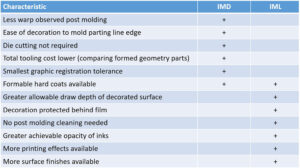
The heat of the molding resin activates the adhesive to bond to the molding resin and release the decoration from the carrier film. When the mold opens, the carrier film is peeled automatically from the molded part, leaving the decoration bonded to the resin. Cleaning is needed on the parting line edges to remove any residual decoration flakes. Because the decoration goes through the parting line of the mold, the decoration can go all the way to the parting line. It is much more difficult to achieve this condition with the IML process as the applique can be crushed in the parting line of the mold. A comparison between IMD and IML can be found in Figure 3.
In-Mold Electronics

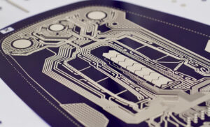
Adding IME to a decorated part is the natural progression of in-mold technology (see Figure 4). OEMs are realizing that if they already are investing in an IML decorated part, the incremental cost of adding circuits provides a cost savings in the subassembly that previously would have included a circuit board, fasteners and multiple parts.
Taking a legacy assembly that might have had multiple mechanical switches and converting that to one IME part with capacitive touch are examples of where these types of IME parts will thrive. Large appliance control panels that often have more than 10 model variants – and potentially a large injection mold for each variant – now could have one mold design to create all variants, including any future configurations for a model refresh.
The form factors and design envelope for these parts are no longer limited to planar PCBs. Now it is possible to design with similar abilities as the formable inks and films used in a regular IML part. Overall assembly thickness can be reduced using IME designs, allowing for new applications where space is limited.
Conductive traces are added to the applique so they are encapsulated between the film and the molding resin. This protection creates very durable and robust electrical circuits. Layouts for traces must include all design considerations for IML, including ink erosion, forming depths and interlayer adhesion.
Where failure of the decorative layer might create a visual annoyance, failure of the traces will create a much more severe user experience if the power button stops working or an indicator light does not function. End-of-line testing during the IME production processes is necessary to check 100% of electrical component functions.
Proper environmental testing should be undertaken to push the traces and connectors to their limits to ensure minimal field failures. Extreme temperature cycling (-40°/+85° C) is a good torture test to identify any weak spots in the design.
Conclusion
In-mold decoration continues to progress with ever-more complicated designs and manufacturing processes. There are many options available to decorate almost any molded part using in-mold decoration. Material suppliers, printers and molders have been working together to discover incremental improvements to push the limits of what can be achieved. The in-mold product development road has been littered with failures, but the future has never been brighter for in-mold decorated manufacturers and their supply chains.
Paul O’Hearn is the engineering manager for Profile Plastics, an injection molder that specializes exclusively with in-mold decorated parts, including the IML, IMD and IME processes. With headquarters located in the greater Minneapolis area, Profile Plastics has been designing and manufacturing challenging decorated parts for almost 30 years.
More information: www.profilemn.com


