
by Jeremy Williams, Trainer/Consultant
RJG, Inc.
There are those who are good at what they do, and then there are those who are the absolute best. The gurus. How are they so good? What do you need to know to be on that higher level? In this article, we’re going to review several of the often-overlooked technical arenas that are vital to understand in order to become a plastics guru.
Mechanical
There are many areas that require a deep understanding of mechanics in the industry. Here, we graze the surface of what you need to know about the machine, the intensification ratio and the mold.
1. The Machine
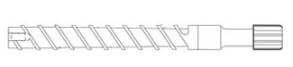
Did you know that 80% of the energy required to melt the material comes from mechanical friction? The first step is understanding the length to diameter ratio (L/D) (a comparison of its flighted length to diameter) in conjunction with the compression ratio (the reduction in depth of the space between the root diameter and outside diameter of the screw).
Figure 1 helps to understand if the design is efficient enough to melt the pellets before they are injected into the mold. Imagine rubbing your hands together on a cold day to generate heat. The faster your hands are rubbed together, the greater the heat. If they are pressed together firmly, the heat generated increases yet again. The reciprocating screw design works the same way. If a screw design is too aggressive, it can cause degradation. If it isn’t aggressive enough, it won’t work the way it needs to. So, it’s vital to find the right balance.
2. The Intensification Ratio
The next type of mechanical advantage that must be understood on the molding machine is the intensification ratio. This ratio determines the amount of work, or power, the injection unit can deliver during the filling and packing phase. Hydraulic machines generally have large diameter cylinders in small diameter screws. If we compare the area of the hydraulic cylinder to the area of the screw, the intensification ratio can be calculated. If this step is overlooked, the molded part may require more power than the machine can deliver, yielding an inconsistent process.
For example, if we apply 500 PSIh hydraulic pressure to a 10:1 ratio, the result is 5,000 PSIp. When the same pressure is applied to a machine with an intensification ratio of 15:1, the result becomes 7,500 PSIp. Think of it like a magnifying glass.
3. The Mold
Now let’s center our attention on the mold and its mechanics. Many parts today are designed with undercut features that require movement of components, such as slides or lifters. It’s important to understand minimum and maximum angles for either to ensure the steel can be disengaged from the molded part. If the angle is too steep, there could be galling between the metal components. If it’s too shallow, the distance of travel required to release the part could negatively impact the mold size or place excessive stress on the lifter rod or cam pin.
Electrical
To a certain extent, a plastics guru needs to have an understanding of how electricity is used in the machine as well as in the mold. First, you should know that machines with hot runners have heaters (pretty obvious, right?). The heaters are used to preheat the screw and barrel assembly before screw rotation can occur. If the heater bands are not properly sized, it can take a long time before production can begin. The heater bands also provide a small amount of energy to melt the plastic material. Understanding how to size the heater and how to verify the proper function can go a long way in making sure the machine is performing appropriately, increasing the opportunity for quality parts each cycle.
Now for a moment, let’s focus on the heaters inside the mold. Hot runners have many heaters to maintain the temperature of the melt from cycle to cycle. Think of them as an extension of the barrel, only smaller. If the heater is not functioning properly, it can cause the temperature to drop and the injection to increase, causing fulgurations in the process. When the temperature runs too hot, from either an improper set point or pinched thermocouple wire, the material inside the system can be degraded.
Fluid dynamics
Before we dive too far into this area, we are going to consult our old friend, the dictionary. We need to make sure everyone has the same understanding of the definitions to the terms we are going to be discussing.
Fluid dynamics: The properties of fluids in motion. There are two different types of fluids: Newtonian and non-Newtonian (shear thickening or shear thinning), along with understanding viscosity, as shown in Graph 1.
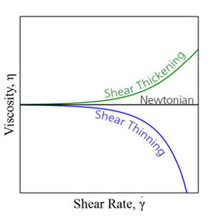
Viscosity: The resistance to flow. The more the fluid resists flow, the higher the viscosity. Shear rate: The change in velocity of parallel planes in a flowing fluid. Picture a river and how the water flows differently near shore in comparison to in the center of the river. At the edges, the water flows slower. Out in the center of the river, water flows faster and has higher shear rates.
Now that we have that out of the way, let’s look at three common fluids within the plastics industry.
First, we will focus on a Newtonian fluid, such as hydraulic oil, which is used to create linear or rotary movement on the machine or mold. If you have ever worked on a car, you may have noticed some oils flow easily while others not so much. The oil that is used in the motor is typically 5W-30. The 5 denotes the weight of the oil, which correlates to the viscosity. Lower weight equates to lower viscosity, which means it flows easier. Oils that are used in the rear differential are typically 75W-90. These oils have a viscosity 15 times higher than oil used in the motor. The motor oil will typically flow relatively easily from the container, while the rear differential oil needs to have the bottle squeezed to make it flow.
Another Newtonian fluid is water, typically used to control the temperature of the mold. If the temperature changes for either water or oil, the viscosity will change as well. However, the line will still be plotted across the graph from left to right – it will just be shifted up or down based on the direction of temperature change.
No matter how fast the fluid moves (shear rate), the viscosity will never change in a Newtonian fluid. This is why the rear differential oil requires the bottle to be squeezed the entire time.
Now, let’s focus on non-Newtonian fluids, specifically shear thinning fluids, such as ketchup and plastic. Wait, what? Ketchup? Let me explain.
For those who have used a glass ketchup bottle, you may have seen the correlation with plastic without knowing it. If we removed the lid and turned the bottle upside down, not much would happen on its own. If we pounded the bottom really hard or inserted a knife, the ketchup would pour onto the plate. Tapping firmly on the 57 (the correct method), the ketchup would then flow at a more desired rate. Before doing any of the previous mentioned methods, the ketchup molecules were all entangled with each other, like a plate of spaghetti. They refused to flow in a timely manner. By applying a force, these molecules started to align, reducing the viscosity and allowing the ketchup to flow from the bottle.
With melted plastics, the same type of behavior is exhibited in the barrel after the pellets have transitioned from solid to liquid form. The faster the flow rate of the machine (shear rate), the lower the viscosity becomes because there is more alignment of the plastic molecules.
There are always limitations, and plastics are not exempt from this. Every plastic has a shear rate limit, and it must be taken into consideration when designing the mold and selecting a flow rate for the molding process. The viscosity of the plastic within the cavity is always changing due to different shapes and thickness and is constantly being cooled by the mold. To measure the viscosity in the molding process, we use the following formula: Effective Viscosity = Fill Time (seconds) x Pressure at Transfer (PSIp)
This allows us to track viscosity shifts from cycle to cycle as well as from lot to lot. By understanding the viscosity of the resin under given conditions, we can predict what type of part quality will be produced.
Thermodynamics
We need to take another brief revisit to our old friend the dictionary, just to make sure we are all on the same page:
Thermodynamics: Physics that deals with heat and other forms of energy.
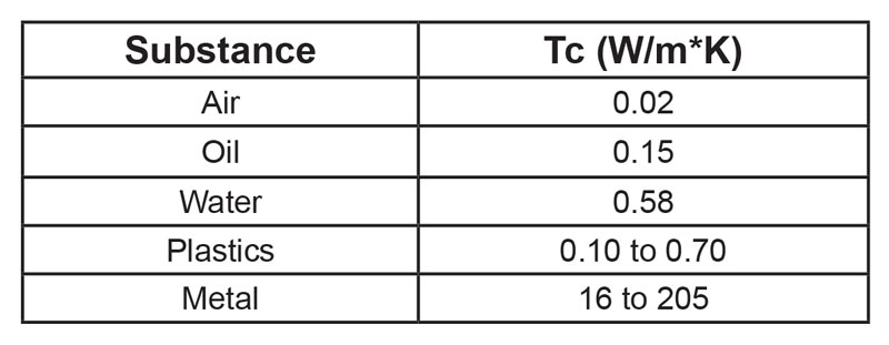
Thermal conductivity (Tλ): The rate in which heat can be conducted through a material.
Table 1 provides a general range for common substances in molding.
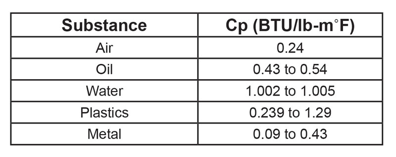
Thermal expansion: How much a material will expand with a given temperature. Specific heat (Cp): The heat required to raise the temperature of the unit mass of a given substance by a given amount. A general range for common substances in molding can be found in Table 2. Shrink rate: The amount a thermoplastic will shrink when cooled.
The machine is responsible for putting energy into the material through screw rotation to force the pellets from a solid state to a liquid state, then reversing the process in the mold.
Earlier, we discussed the L/D and compression ratios of the reciprocating screw. These play a key role in determining how much mechanical energy is put into the plastic. If there is too much energy put into the plastic, there is high potential for degradation. Conversely, if energy is inadequate, expect to see unmelted pellets in molded parts. A plastics guru can change the screw RPMs and back pressure during recovery, which affect the amount of energy put into the plastic. They must understand that not all polymers melt at the same rate, and some are very sensitive to heat.
The majority of the molding cycle (nearly 80%) is waiting for the plastic to reach a temperature low enough that it’s rigid enough to withstand the forces of ejection. The workhorse for this is none other than the mold. Thermal conductivity of the mold metal also is critical. Not all metals transfer heat at the same rate, with stainless steel being very poor and copper alloys being very good.
Only about 40% of energy is released from the part due to the ability of plastic to transfer heat. As the molding cycle progresses, the plastic becomes more of an insulator with every passing moment, making it harder and harder to remove heat.
When large molds run very hot, thermal expansion calculations must be used to ensure there is adequate clearance between moving components at operating temperature. Generally, the larger the mold and the higher the temperature, the more there is a concern. If the mold contains a hot runner system direct of valve gate, the thermal expansion at operating temperature must be addressed or there could be severe mold damage.
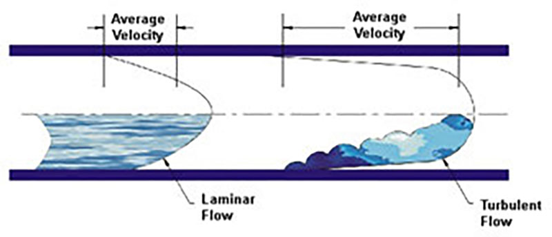
It also is critical to understand how the energy is removed from the molded part. One method of heat transfer is through the air surrounding the mold, which is not very efficient. Heat also is removed via the water channels. It’s important to have achieved turbulent flow in the channel to improve the ability of the water to transfer heat.
If the Reynolds number is calculated, it can be determined if the water is flowing in a laminar or turbulent way (shown in Figure 2).
Metallurgy
A surprising amount of metal is used in the manufacture of plastic molded parts. On the molding machine, one key area that must be considered is the screw and barrel assembly. It takes a significant amount of energy to melt plastic through mechanical friction, but the type of resin being melted impacts the steel selection.
For general purposes (materials such as polypropylene), a standard steel will work just fine. However, not every material is as easy to work with. Materials that have glass fillers can quickly erode a soft steel selection, causing all kinds of havoc on part quality. For aggressive materials, such as a 33% glass-filled PA, it’s recommended the screw and barrel assembly be constructed of a CPM 9V or similar type steel, which has a higher wear resistance.
Tie bars are another important feature on the molding machine. Tonnage is created when these massive steel rods are stretched in tensile. All four rods must stretch equally to provide even clamping forces across the mold surface. If the difference is large enough, it can cause premature failure of the mold or even cause a tie bar to snap. Speaking from experience, neither of these situations is pleasant.
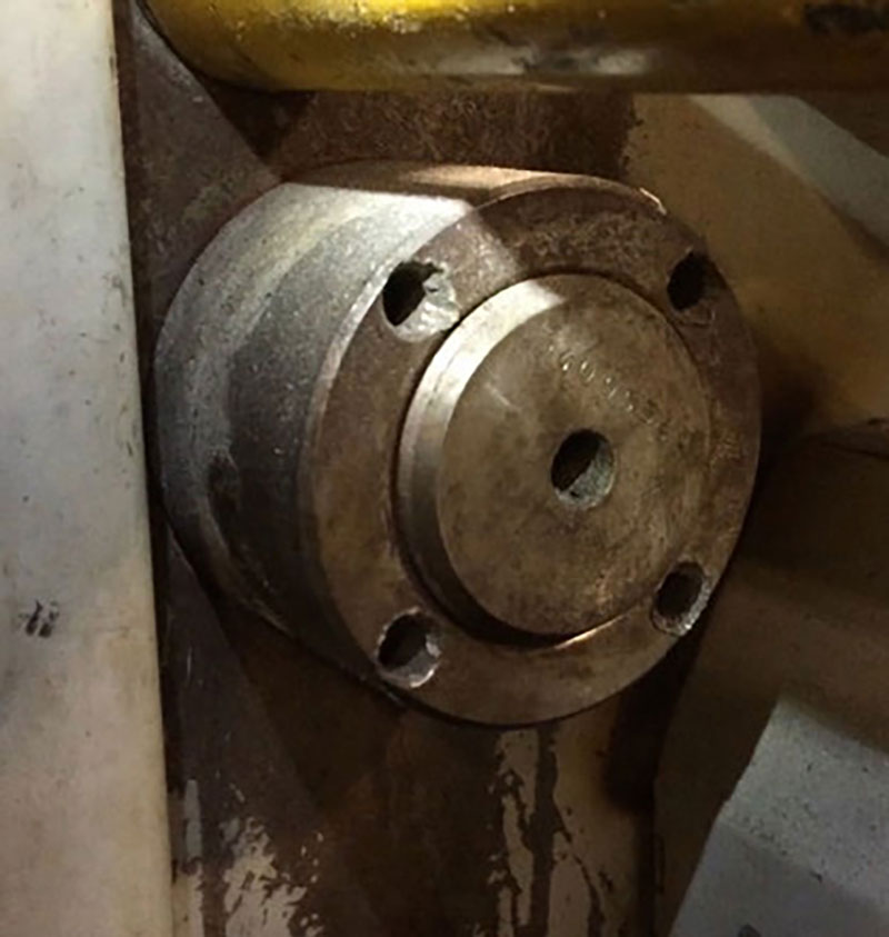
In Image 2, there is a visual gap between the back of the platen and the tie bar nut. In this example, the machine was set to run at 50 tons. With 4 tie bars, each should provide 12.5 tons of force, however due to improper torque, the tie bars were stretching at different rates. Platen stiffness is critical to the overall longevity of both the mold and the machine. Platen must be stiff to provide a rigid structure for the mold to be pressed against during injection. This is completed with two factors: the type of metal that is selected and the shape of the support structure opposite the mold mounting surface.
If the platen is not properly designed, the mold will typically flash around the sprue. This is because the highest pressure is at the sprue and the least amount of support is typically in the center of a toggle-type clamping system.
Understanding the material that is going to be processed also impacts the cavity and core steel selection. When processing materials that are abrasive, such as the 33% glass-filled nylon mentioned earlier, choosing the appropriate mold steel is critical. In this instance, selecting a steel like H13 with a high Rockwell hardness will improve the overall durability. Conversely, when molding a PP resin, a P20 likely will be the correct choice for the application – it is softer and transfers heat more effectively.
One item to keep in mind is the balance between hardness and thermal conductivity. In certain circumstances, such as in the medical arena, processors might be forced into using something like stainless steel, which does not transfer heat well. For injection molders, time is money. When a steel is selected that doesn’t transfer heat well, the ability to achieve cycle times becomes increasingly difficult.
Conclusion
Don’t be fooled – plastics gurus possess no superpowers. They may not even be masters of all of these areas. But gurus are able to see plastics from many different perspectives, which allows them to better understand the situation and how to apply the appropriate solution. You, too, can become a guru with enough training and practice.
Jeremy Williams has more than 17 years of experience in the plastics industry serving the medical, automotive, furniture and appliance industries. He previously worked as a principal engineer, taking projects from design concept to saleable products. Williams earned his Master Molder II qualification in 2011, became an RJG Qualified Trainer in 2012 and started at RJG in 2015. In addition to his extensive manufacturing background, he holds degrees in plastics and business. Currently, Williams is a Consultant/Trainer with TZERO®.
More information: www.rjginc.com